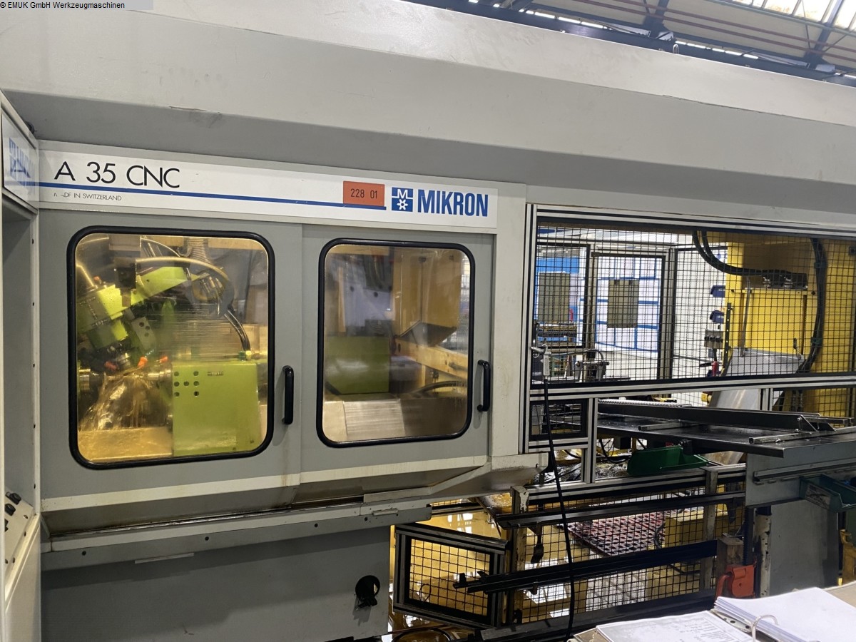
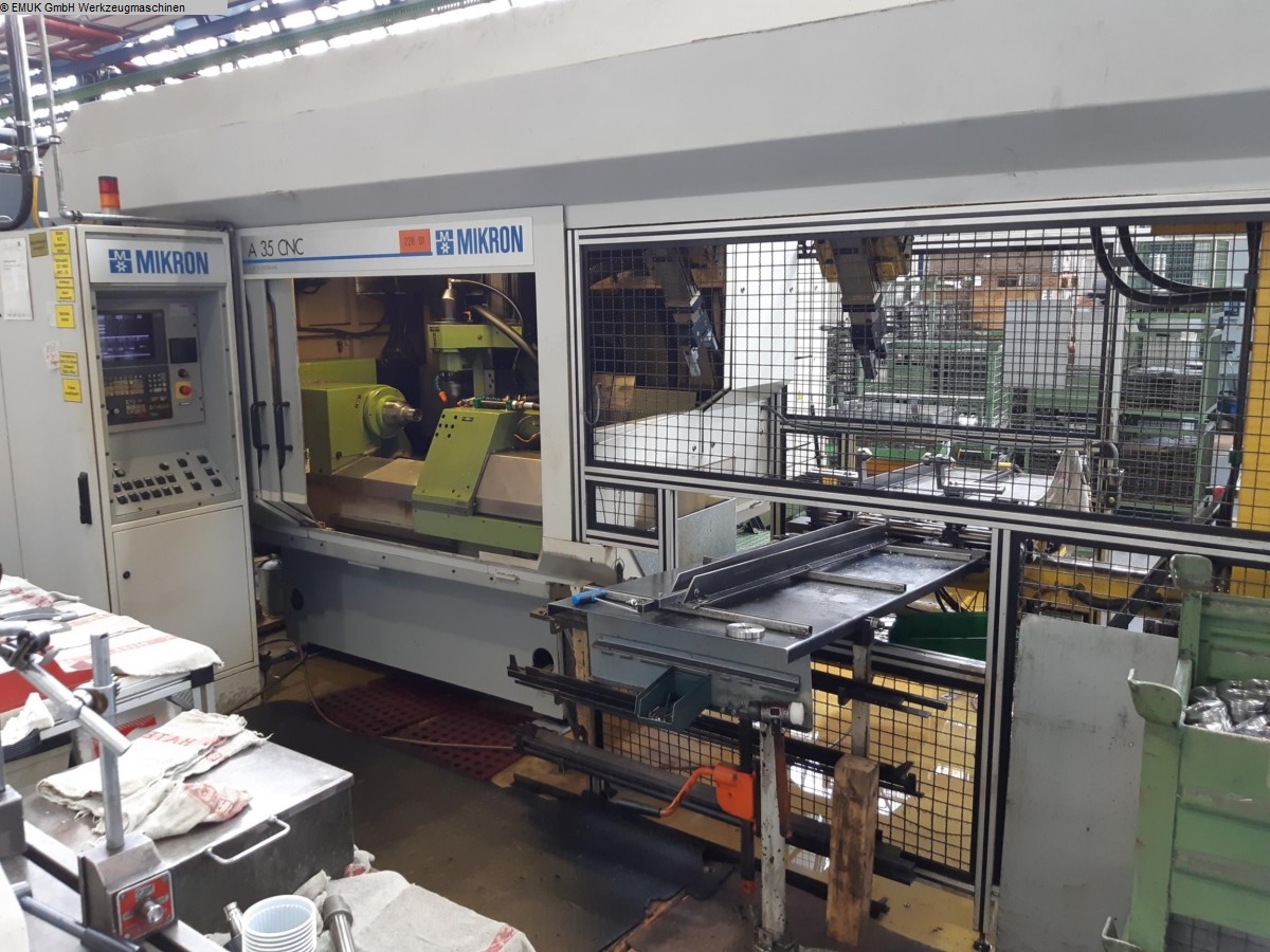
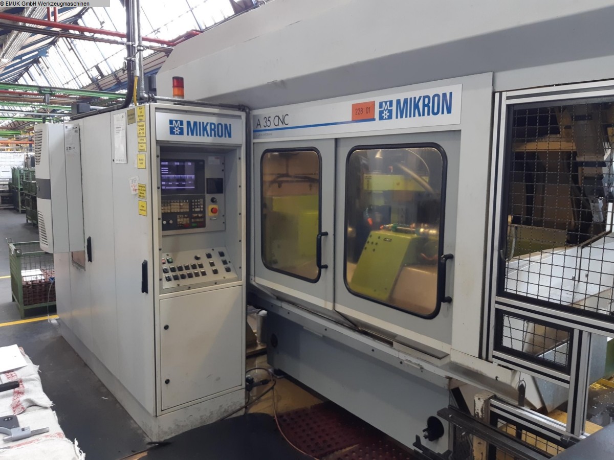
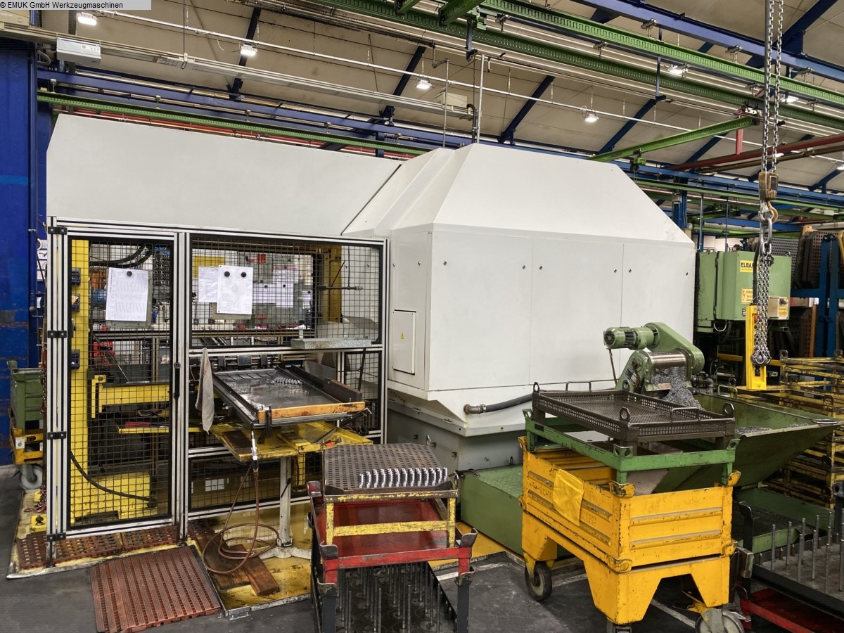
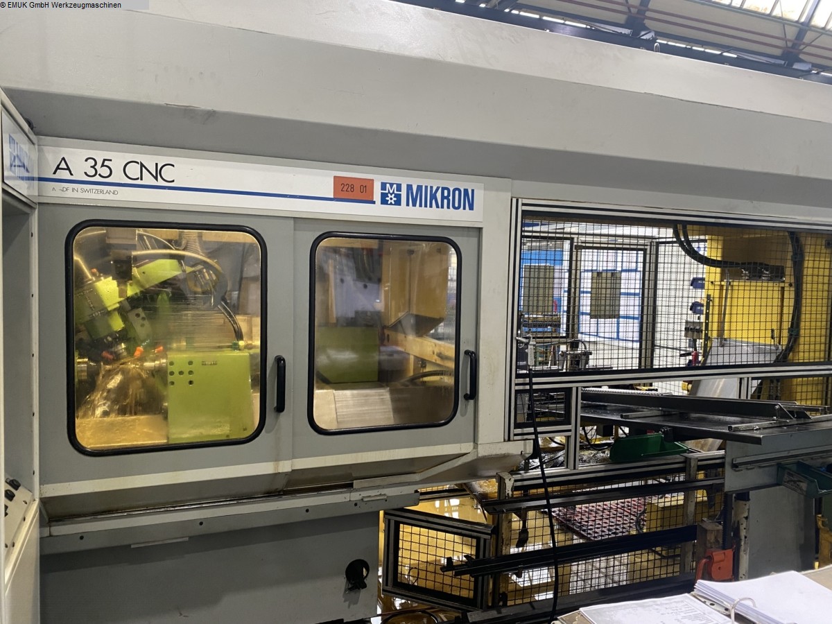
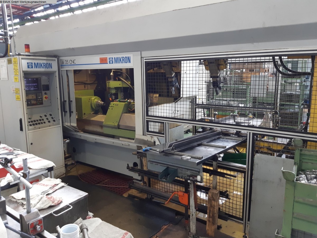
MIKRON A 35
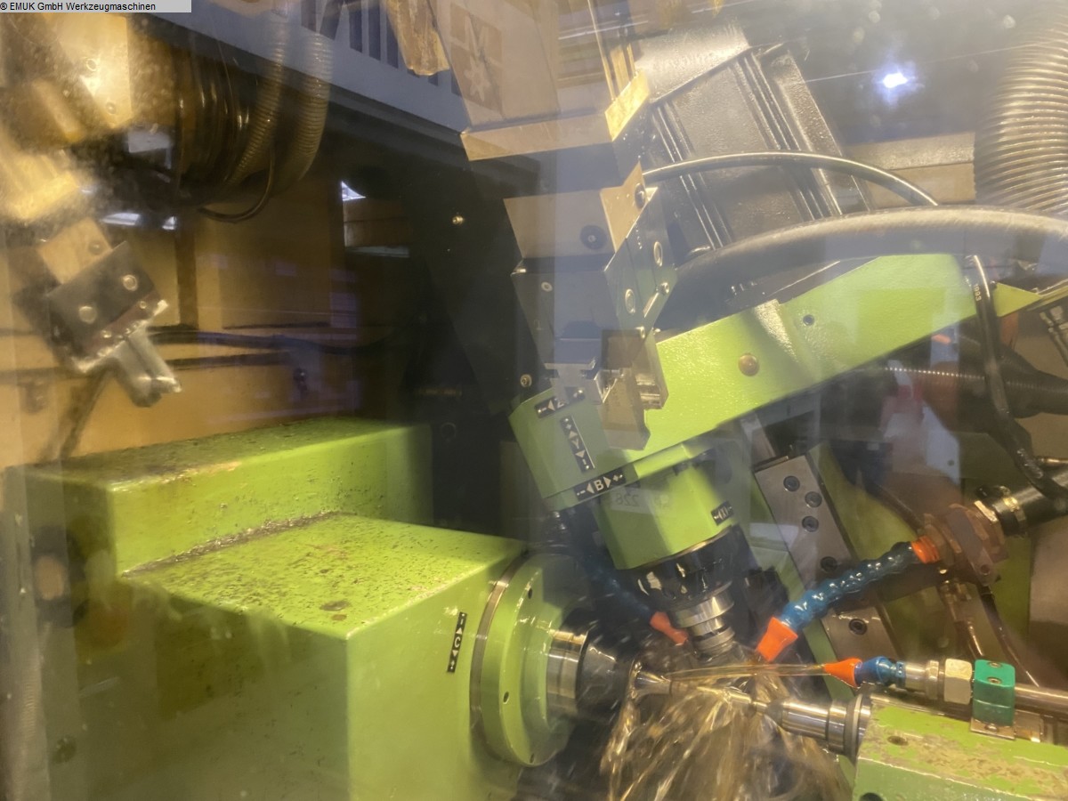
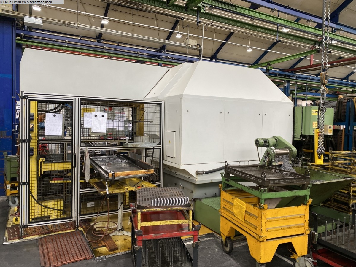
The design of the basic machine is characterised by the following features:
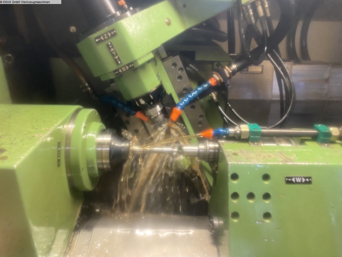
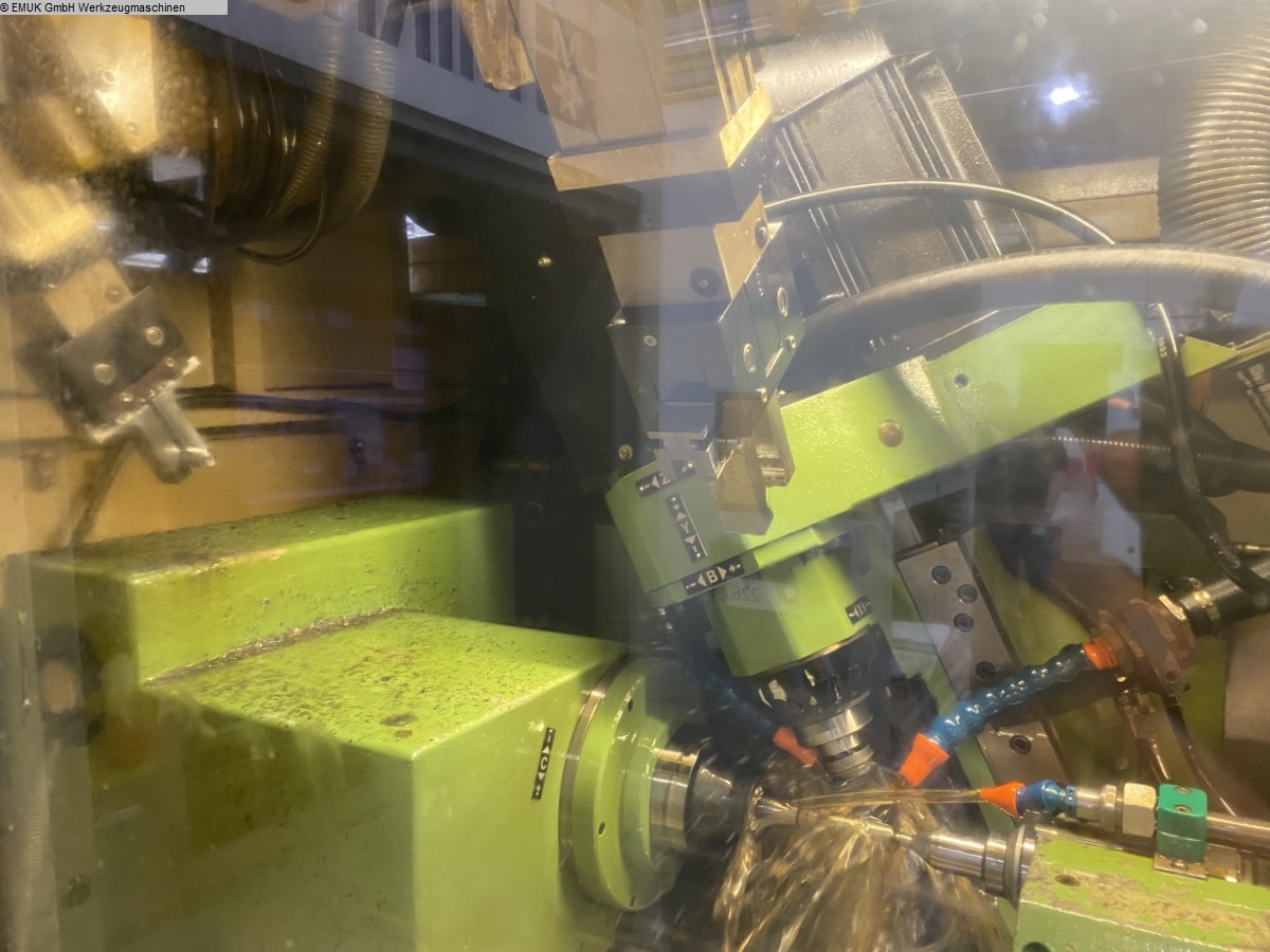
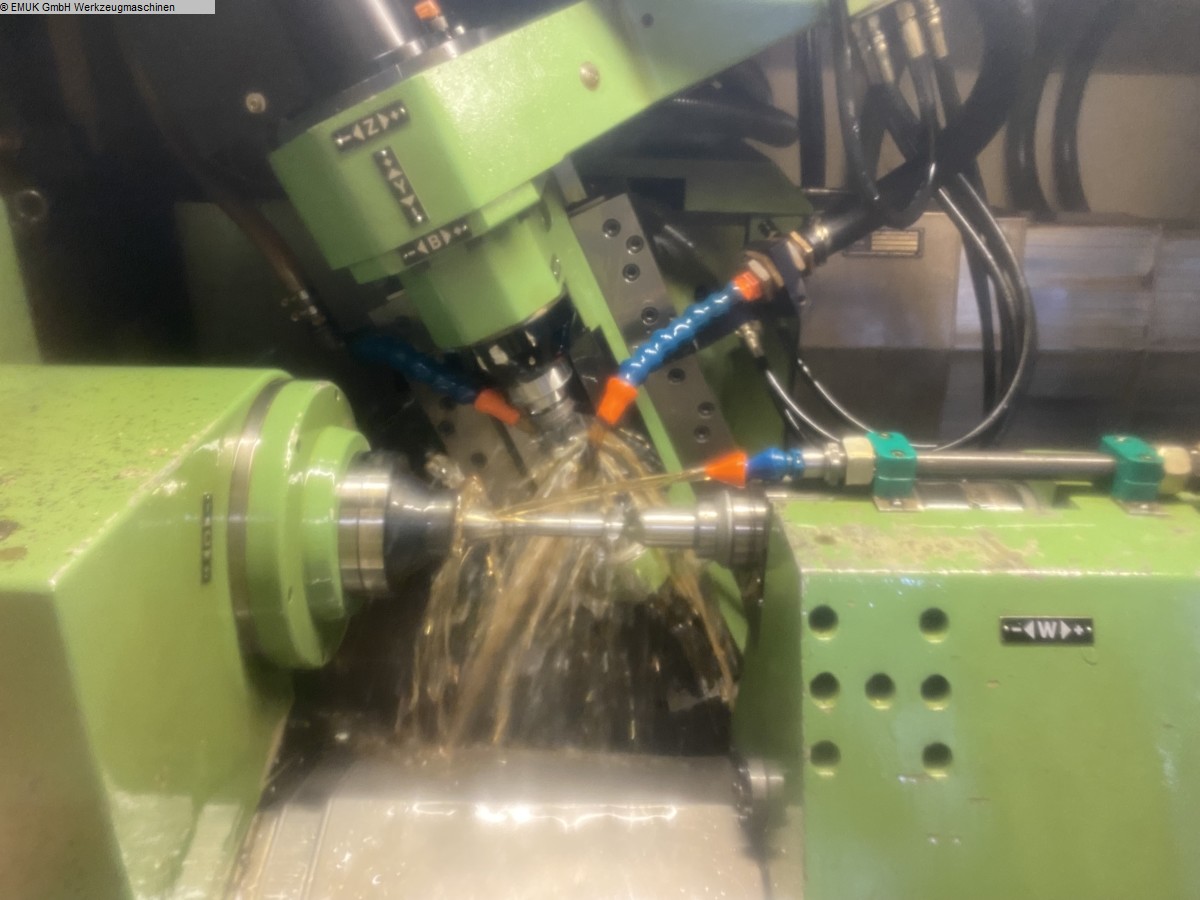
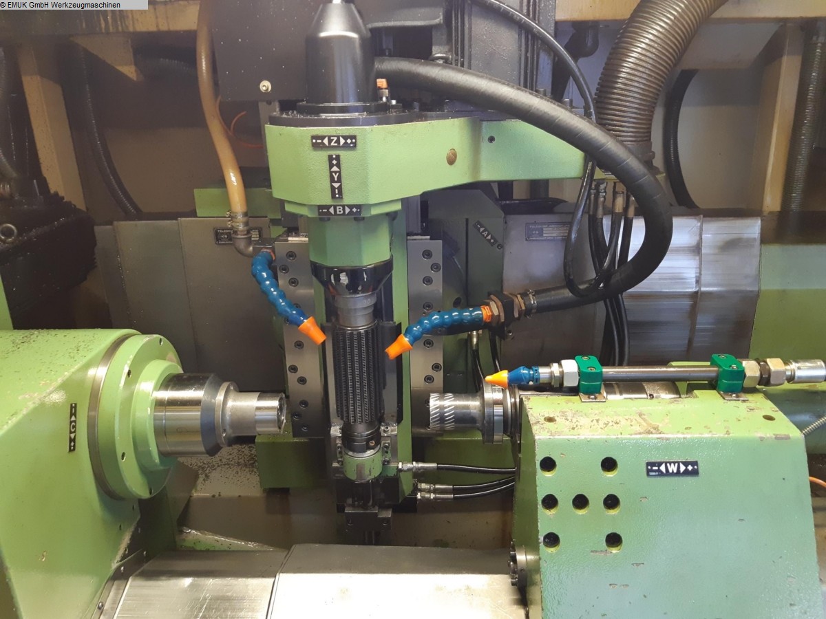
- horizontal position of the workpiece spindle; vertical position of the
milling spindle or milling head of the milling head
- The workpiece is held between the workpiece headstock (left) and the
tailstock (right).
- the radial slide is mounted on the base (X-axis)
- the axial slide moves on the radial slide (Z-axis)
- the shift milling head is equipped with an automatic angle adjustment
(A-axis); the shift slide (Y-axis) moves diagonally to the workpiece diameter
- CNC controlled
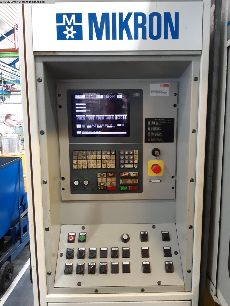
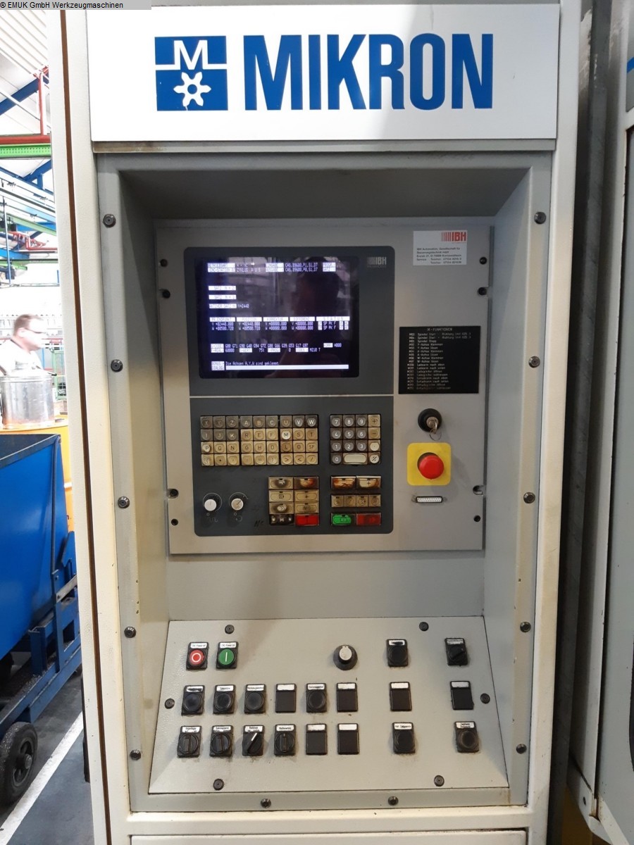
- IBH control
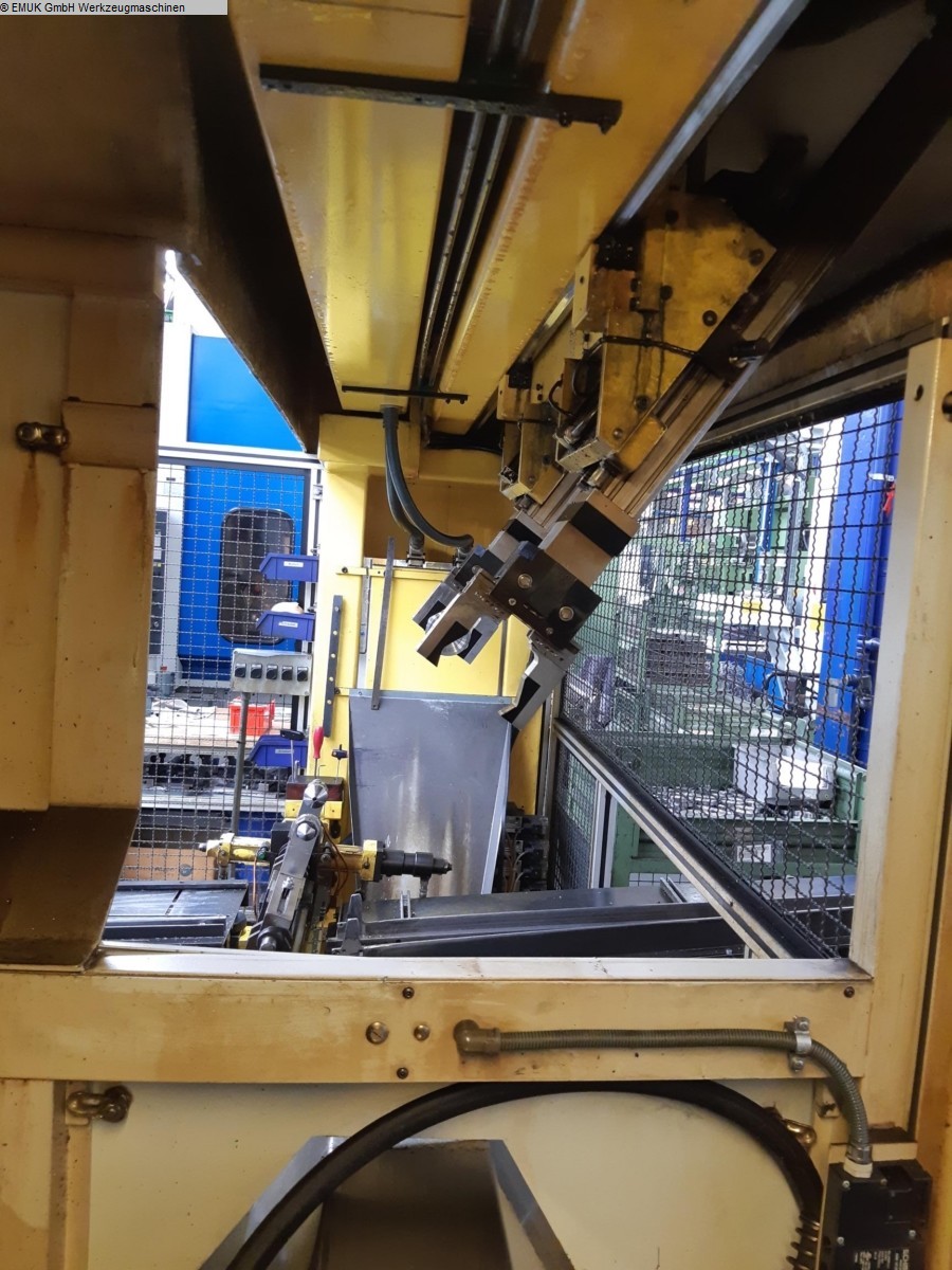
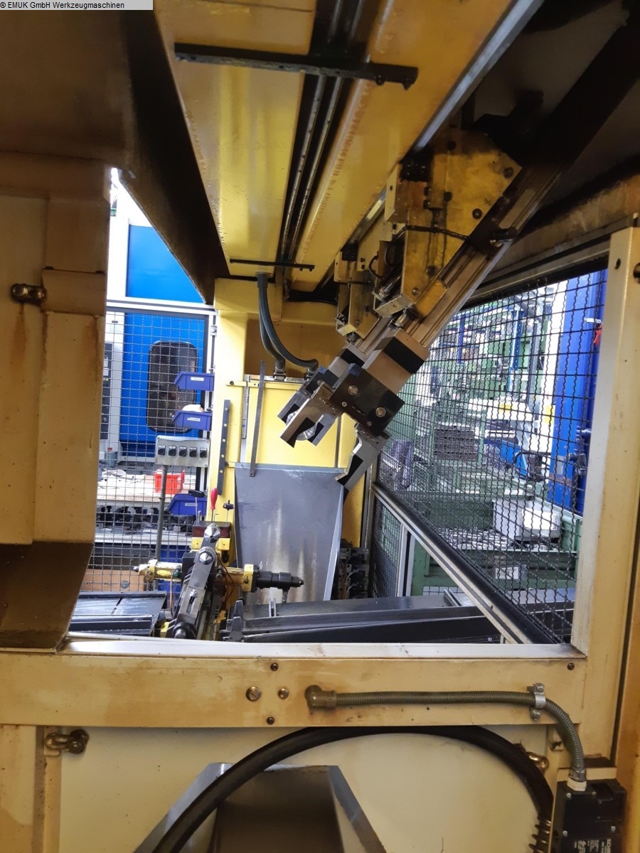
- loading device
- Many accessories
Technical data:
- largest milling module with hobs according to DIN 8002: 4.5 mm
- largest milling module for high-performance milling: 3.0 mm
- Number of teeth: 2 - 999
- max. workpiece diameter for manual loading: 200 mm
- max. workpiece diameter for automatic loading: 150 mm
- maximum workpiece length: 400 mm
- largest / smallest milling cutter diameter: 102/40 mm
- maximum cutter length: 230 mm
- largest / smallest milling arbor diameter (standard): 32/16 mm
- Axial slide path = largest milling length Z-axis: 300 mm
- Radial slide path X-axis: 140 mm
- Milling cutter shift path Y-axis: 100 mm
- Milling stock path W-axis: 420 mm
- Swivelling angle of shift milling head (left/right) A-axis: 50°/60°
Milling coordinates:
- Z-axis: 100 - 400 mm
- X-axis: 1ß0 - 150 mm
- Y-axis (end face of milling spindle): 50 - 230 mm
- W-axis (face of tailstock spindle): 165 - 585 mm
- Milling cutter speed range standard B-axis: 0 - 1500 rpm
- Workpiece speed C-axis: 0 - 350 rpm
Feed speeds:
- X-axis: 3500 mm/min
- Z-axis: 3500 mm/min
- Y-axis: 4000 mm/min
- W-axis: 5500 mm/min
- V-axis (gantry loader): 80000 mm/min

